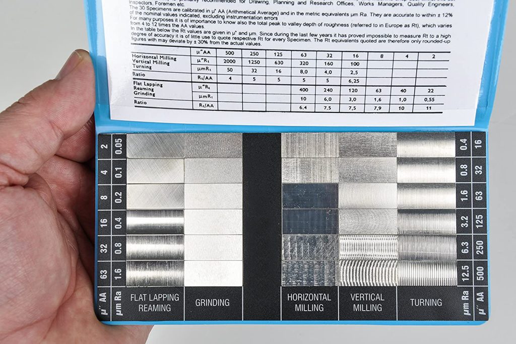
For decades machinists have used tactile gages (comparator gages) to quantitatively track surface finish as they machined their parts. Tactile gages reference to common machined textures, such as milled, ground, and polished metal. For tracking a process, these gages are just a first step to controlling surface texture. They serve a function, but they have limitations.
A “measurement instrument” with wide error bars
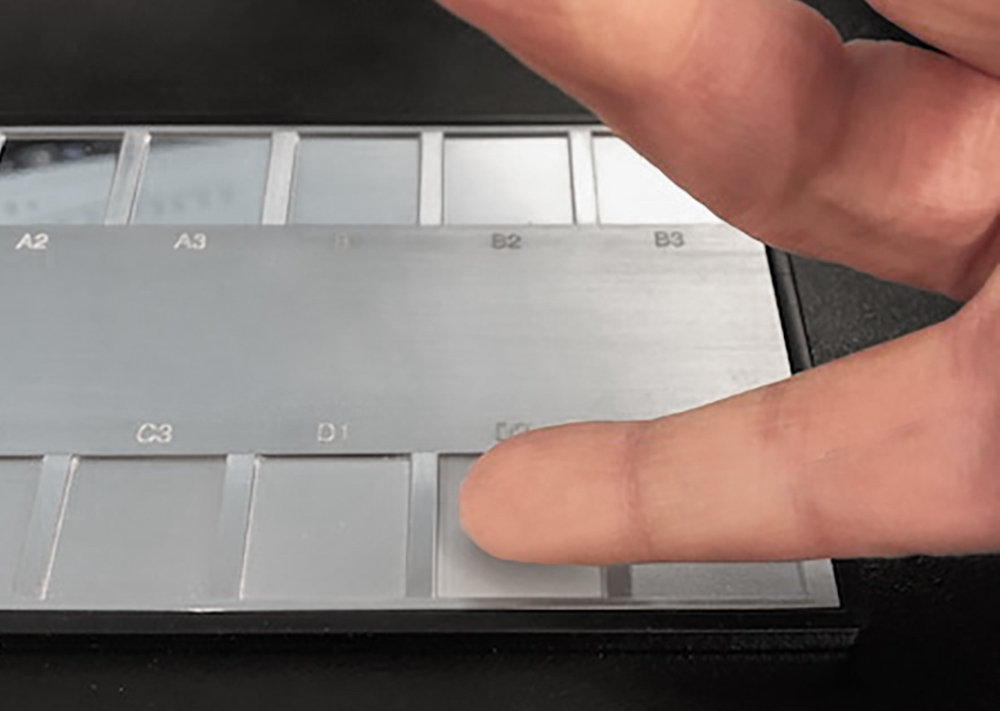
Tactile gages were developed at a time when there were essentially no other methods available to describe surface roughness in the shop. The gages were made by casting the textures of actual working parts, then replicating that surface to create an in-house master. The goal was to allow machinists to duplicate a known-good surface through visual or tactile comparison.
The challenge is that visual and tactile inspection are highly subjective and vary greatly even among highly trained inspectors. When the inspector is the “measurement instrument,” many factors can alter the results, ranging from the quality of the lighting and the temperature in the factory, to variations in the inspectors’ tactile sensitivity.
A guide…but not a ruler
A tactile gage often includes a code to indicate the type of machined surface and the relative amplitude of the surface roughness. “125M” and “63M,” for example, may represent milled surfaces with roughness amplitudes of 125µin and 63µin respectively.
Trouble can occur, however, if these values are used too literally. While the codes may be associated with Ra (average roughness) values, stylus or optical profiler measurements of these surfaces may vary significantly. In most cases, the numbers should be treated as comparative values rather than standards.
Another issue with relying on comparator gages is that critical aspects of the surface texture are not represented. A change in orientation in the machining process, for example, may result in a leak path that never existed before. A change in waviness will go completely undetected when only the roughness is inspected. In these cases, the parts may continue to pass all specifications—just as they did the day before—but they may now begin to fail in the field. A comparator gage alone will not help you spot these critical changes.
Visual inspection will always be a useful part of an inspector’s toolkit, as a fast way to assess whether a process is operating normally. Comparator gages can help for such quick process checks. But to truly hold a process in control, we need to specify parameters that describe the aspects of the texture that matter for the application, then measure those parameters with instruments that can provide reliable, objective, quantitative data. The combination of an experienced eye and measurable verification will always provide the optimum results.