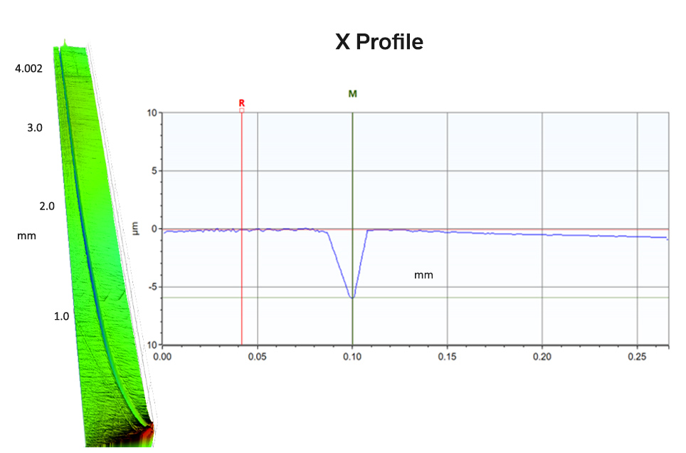
In the molding process, knit lines form where the material does not weld together seamlessly as it moves through the tooling. The cause may be related to the mold surface, thermal effects, variability in material amounts, etc. The result can be a dip or ridge in the molded surface, which can lead to a number of functional problems in the field.
Leak Paths and Interrupted Flow
The primary concern with knit lines is that they can create paths for fluid to leak into or out of an interface. In the case of a molded coupler for attaching a hose or tube, a knit line across the face can prevent the interface from properly sealing. The image below shows a measurement of a knit line on the molded surface of a fluid delivery device. The imperfection, while only a few microns deep, was sufficient to form a leak path. This type of leak could lead to warranty and recall issues for a wide range of components, from engines and seals to medical devices and consumer goods.

A stitched image of a knit line in a molded device.
In addition to causing leaks, knit lines can also interfere with the smooth flow of liquid across a surface. In devices that transport blood or other fluids, the non-laminar flow can impact performance and lead to premature wear or failure.
High resolution measurement helps uncover the cause
Accurate measurement of knit lines is essential for quality control. A 3D optical profiler has sufficiently high lateral and vertical resolution to measure knit lines on components, even on highly curved or complex surfaces. Unlike a stylus measuring system, the non-contact optical technology ensures that softer materials are not damaged during the measurement process.
But a leak path on a component’s surface is a symptom; the cause is in the molding process. The finish of the mold as well as the physics and chemistry of the molten plastic flowing through the mold/tool can all cause flow differentials that can lead to defects. Measuring the mold surface texture directly can be the most effective way to determine how the material is flowing and forming against the mold surfaces. Most measurement systems cannot accommodate large, heavy, and complex molds, however. Measuring the mold surfaces requires complicated fixtures or the slow, messy process of creating and measuring replicas of the surface, The Bruker NPFlex 3D optical profiler (shown below) that we use at Michigan Metrology has a swiveling measurement head and long working distance objectives that make it possible to quantify features in challenging areas of a mold or molded component.
