Cutoffs define the band of spatial wavelengths that will be included in the calculation of surface texture parameters. As we’ve stated often in this blog, a parameter value (e.g., a value for Average Roughness, Ra) specified without cutoffs is essentially meaningless. Very different surfaces can produce the same Ra value, and the same surface with different cutoffs can give wildly different Ra results as well. This is why standards such as ASME B46.1-2019 require that the cutoffs be specified.
Nevertheless, despite standards and best intentions, at some point you may encounter a drawing that calls out a parameter but provides no cutoffs to define it. So, what do you do?
Contact the designer
The component’s designer is the presumptive expert for the part, and for which spatial wavelengths matter to the part’s function. The designer should specify cutoffs, not the person measuring the parts. Therefore, whenever possible, the first step to determine missing cutoff values should always be to turn to the part designer.
Follow the procedure called out in the standard
If the designer is not available, the ASME B46.1-2019 specification provides a set of steps to follow to determine the most appropriate cutoff value.
For a periodic surface
If the surface texture is reasonably periodic (e.g., a turned or milled surface with a highly repetitive pattern):
- Measure the surface without any filtering applied.
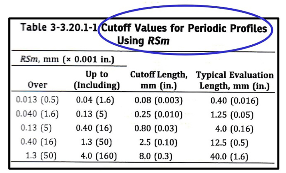
- Determine the dominant periodic spacing, either by reading the spacing from the profile or by calculating a spacing parameter such as Rsm.
- Use the table in the B46.1 specification to determine the cutoff length.

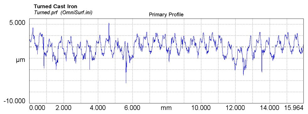
As an example, in the turned surface shown below, we can see that the dominant spacing is approx. 0.5 mm from major peak to major peak. Referencing the table, we see that this spacing falls within the 0.40–1.3 mm range. Therefore, a 2.5 mm cutoff should be used.

For a non-periodic surface
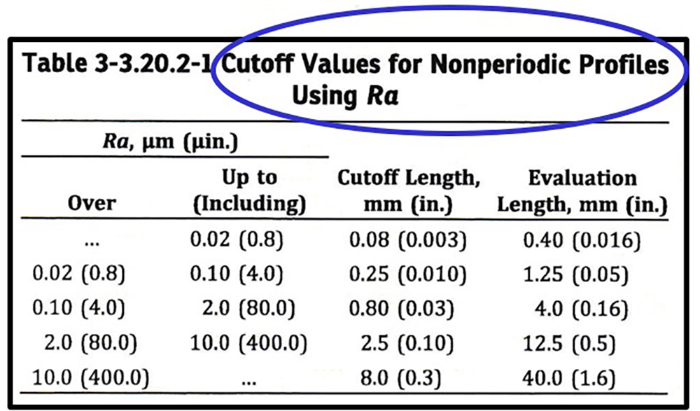
If the surface does not have a periodic pattern, but an Ra value is specified, B46.1 also provides a table to determine the cutoff length.

Take as an example, a non-periodic surface with a 0.2 µm Ra max specification. This Ra value falls within the 0.10–2.0 µm range in the chart above. Therefore, a 0.80 mm cutoff should be used.
Conflicts
In some cases, the table values may not match with your knowledge of the surface texture and its intended application. For example, in the non-periodic surface above, you may know that spatial wavelengths much longer than 0.80 mm will affect the part’s performance. But using the specified 0.80 mm cutoff, you will not even see those long wavelengths. It would seem that you’d want to override the table value and choose a different cutoff…but you CAN’T. The drawing did not specify a cutoff, therefore, per the specification, you must use the value in the table, even if it’s bad science.
This is an excellent illustration of why the designer should include the cutoff value in the first place!
No starting point
If you have no cutoff value and no prior knowledge of the surface, the only remaining course of action is to make the best guess possible:
- Start with the largest cutoff length listed in the “non-periodic surface” table.
- Measure the Ra of the surface.
- From the non-periodic surface table, verify that the measured Ra falls within the Ra range for that cutoff.
- Now, try the next shortest cutoff length. If the Ra value is within range for this cutoff, use this smaller cutoff instead.
- Continue this process until you reach the smallest cutoff length that produces an Ra value consistent with the table. Use this smallest value as the cutoff.
I want to emphasize that this procedure is a last resort! It contains a lot of arbitrariness, and the table ranges are large. You should exhaust all other methods for determining a proper cutoff value before reaching this point.
And, if you do find that you need to resort to this method, document how you came to use the cutoff value! It may prove important if your results are ever called into question.
3D measurement
The procedures described above govern 2D measurement. For 3D measurement, the situation is far murkier, and we will save that for another day…
Want to learn more about cutoff values and how to set them? There’s a lot more information in the Filtering module of the Surface Texture and Tribology short course at udemy.com, or consider taking our next live, in-person class!
Please fill out the form below to download this article as a PDF:
