Many surface measurement projects begin with a similar challenge: parts meet specifications, yet some fail while others function. How can we differentiate between the good and poor parts, to understand what makes the best surface for the application, and to develop processes to manufacture that surface?
In many cases, the successful and failing surfaces can guide us toward those answers. A case study can help explain. In this example, a piston rod was designed to slide through a glass filled polymer bushing. The system needed to form a tight seal to contain a captive gas. But in the field, some parts sealed, while with others, gas leaked through the interface. The good and bad parts all measured within spec for Ra (average roughness). We needed another way to tell “good” from “bad” starting surfaces.
Where does the surface want to go?
In such cases, a good starting point is to measure parts that perform well and look for characteristics of their texture that are absent in failing parts. We let the parts show us what works in the application.
In our case study, we measured a series of rods straight from the manufacturing line. The rods had been ground around their circumference, as in the surface texture measurement below.
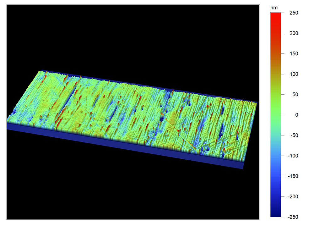
The initial, ground surface of a rod that mates with a glass filled polymer bushing.
We also measured parts that had been used for a period of time. We found that, on the parts that sealed well, the bushing had machined ridges into the rod in the direction of travel, as in the image below. This “final machining” step had created a texture that virtually obliterated the initial texture, replacing it with texture at 90 degrees to the original. These new ridges “dovetailed” with the bushing at a microscopic scale, producing a superior seal.
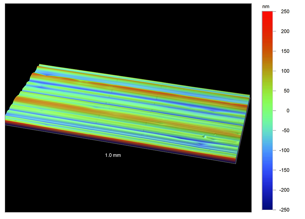
Successful parts showed a pattern of wear in the direction of motion.
How can we help the surface get there?
Once we know what a successful surface looks like, we can try to manufacture a starting surface that will lead to that final surface.
In our case study, we knew that grinding the shaft in one direction then relying on the bushings to machine a perpendicular texture used a lot of energy (and likely shorten the bushings’ life). A better solution might be to grind the rod to the right diameter, then hone the surface in the direction of travel. The goal was to give the surface a head start toward where we knew it “wanted” to end up.
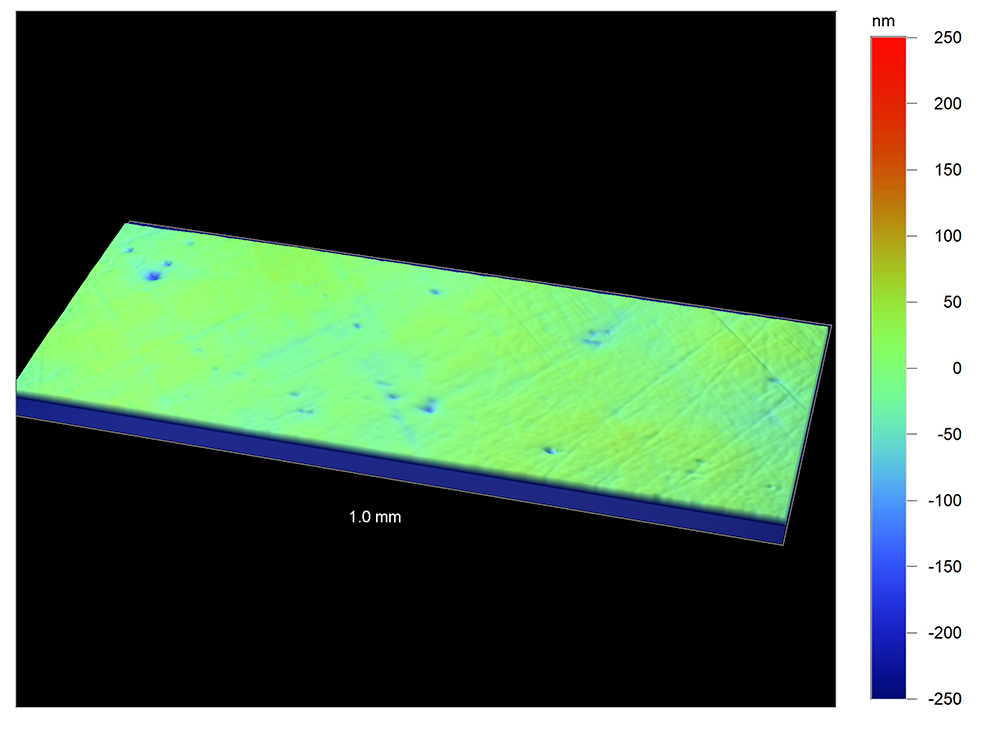
Honing the surface in the direction of travel gave the texture a head start in the right direction.
Run-in as “final machining”
It’s tempting to try to manufacture the “final” surface from the start, which seems like the most efficient approach. But, after running in, a surface that is machined to the final condition may no longer mate optimally with the opposing surface.
Run-in is essentially a final machining step that allows individual pairs of mating parts to develop a unique, optimal interface. However, too much run-in machining can create particulates that ultimately may cause more aggressive wear in the interface. It’s a delicate balance.
In our case study, both components of the texture—the circumferential grinding and the “final machining” in the direction of travel—combined to create the best sealing surface. It’s a great example of how successful surfaces can guide us backwards to the initial machined texture we want.
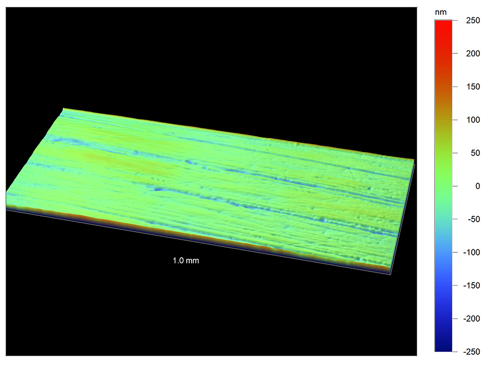
The final run-in surface, after starting with a lower roughness, crosshatched texture.
Do you have an issue with noise, vibration, leaks, squeaks, or other issues? Schedule a free consultation with us to discuss it. We’d be glad to help!