3D Filtering
The measurement dataset consists of an array of values which represent heights at various points along the surface. Depending on the measurement technology such as stylus diameter, optical lens performance, camera resolution and electronics, a minimal spatial wavelength structure may be measured. Typically the smallest spatial wavelength that can be measured consists of 5 measured resolution elements along a given direction. The largest spatial wavelength that can be measured is limited to the full extent of the measured field. For example if a measurement is made over a 1mm lateral region then the largest spatial wavelength that can be ideally measured is 1mm long.
Many applications require only certain spatial wavelengths be included in the calculation of the various texture parameters. For example, a sealing surface may be better understood by considering a limited number of shorter spatial wavelength components since longer spatial wavelength structures may be easily conformed to by a compliant sealing material. Furthermore, to support correlation between different measurement systems it is imperative that the bandwidth of the spatial wavelength structures being measured are the same.
Once a surface is measured a mathematical operation is applied to remove any base form such as Tilt, Cylinder, Sphere, etc. if necessary. This mathematical operation is referred to as an F-operator in that the “form” is removed from the “raw” measurement prior to any additional filtering operations.
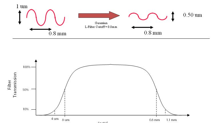
After the F-operator, a Gaussian filter is applied to the data which limits the short spatial wavelength (S-Filter) and long spatial wavelength (L-Filter) structures prior to analysis.
The S-Filter and L-Filter are characterized by cutoff lengths:
For example, a 0.8 mm cutoff-length L-Filter, implies that for structures with a spatial wavelength of 0.8 mm the amplitude presented for analysis is 50% of the amplitude of the unfiltered measured data. For spatial wavelengths greater than 0.8 mm the surface structure amplitudes are further attenuated such that spatial wavelengths components greater than 1.1 mm are attenuated by more than 90% prior to analysis. For spatial wavelengths less than 0.8 mm, surface structure amplitudes are minimally attenuated with wavelength components less than 0.5 mm being attenuated by 10% or less.
As another example, an 8 um cutoff-length S-Filter implies that for structures with a spatial wavelength of 8 um, the amplitude presented for analysis is 50% of the amplitude of the unfiltered measured data. For spatial wavelengths less than 8 um, the surface structures amplitudes are further attenuated such that spatial wavelength components less than 2 um are totally eliminated prior to analysis. For spatial wavelengths greater than 8 um, the surface features are minimally attenuated with wavelength components greater than 11 um being attenuate by about 10% or less.
The following figure depicts the “bandwidth” and attenuation rate (rolloff) for an S-Filter of 8um and L-Filter of 0.8mm. The ASME B46.1-2002 reference includes graphs depicting the attenuation rates (rolloff) for various filter cutoff values.